LED PCB Assembly Services – Substrate & Thermal Management Guide
LED PCB assembly combines aluminum or metal-core substrates, SMD LED placement and thermal management to produce reliable, long-lasting LED lighting boards. PCBELEC helps you understand substrate options, heat dissipation design and quality inspection before you place an order.
High-power LEDs generate significant heat during operation, which makes substrate selection and thermal management the two most critical factors in LED PCB assembly. The guides below explain how aluminum substrates dissipate heat, how to choose the right SMD LED package for your application, and what inspection methods ensure that finished LED boards perform reliably over their rated lifespan.
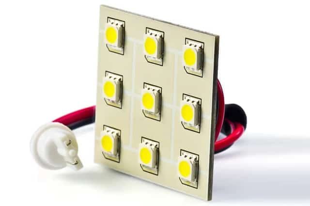
Turnkey LED PCB Board Assembly
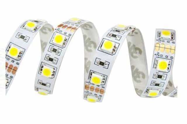
LED Strip Lighting PCB Assembly
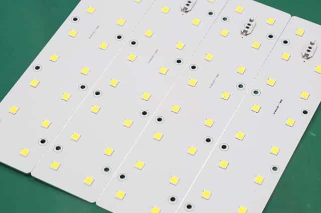
LED Aluminum Base PCB Assembly
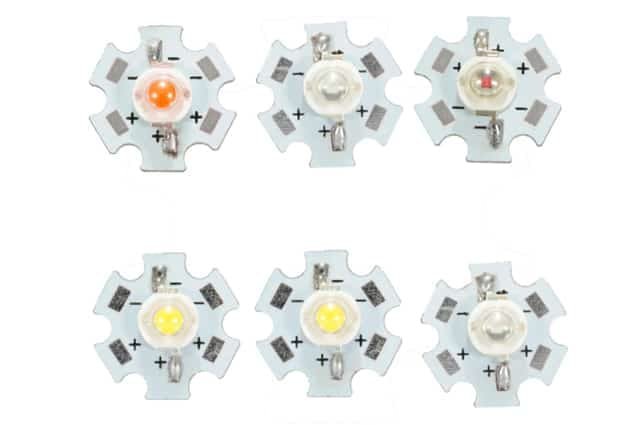
Metal Core PCB Assembly
Thermal Management in LED PCB Assembly: Why Heat Dissipation Matters
Heat is the single biggest factor affecting LED lifespan and performance. Effective thermal management in LED PCB assembly prevents lumen depreciation, color shift and premature failure.
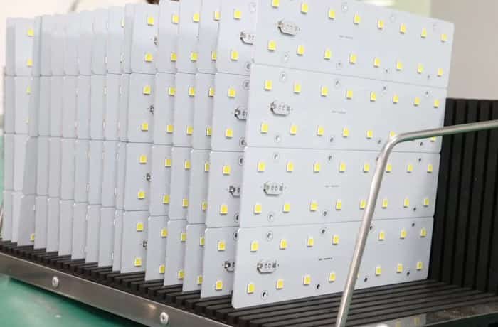
The Problem: Why Heat Destroys LEDs
High-power LEDs generate enough thermal output to degrade components if heat is not managed properly. Three primary failure modes are caused by excess heat:
- Lumen depreciation — Brightness drops below rated output well before the LED's expected lifespan
- Color shift — Color temperature drifts as phosphor layers degrade under thermal stress
- Premature failure — LED junction temperature exceeds safe limits, shortening operational life from 50,000+ hours to a fraction of rated lifespan
How Aluminum Substrates Dissipate Heat
A typical aluminum LED PCB uses a three-layer structure to move heat away from LED junctions without external heat sinks:
- Layer 1 — Copper Circuit Layer — Carries electrical connections between LEDs, resistors and other components
- Layer 2 — Thermally Conductive Dielectric — Transfers heat from the copper layer down to the metal base; this is the critical layer that distinguishes an MCPCB from standard FR-4
- Layer 3 — Aluminum Base Layer— Acts as a heat spreader, distributing thermal energy across the board surface for dissipation into the surrounding environment
Design Factors That Affect Thermal Performance
- Substrate thermal conductivity — Aluminum (1.0–2.2 W/mK) vs FR-4 (~0.3 W/mK) vs copper core (~400 W/mK)
- Copper weight and trace width — Thicker copper improves heat spreading; wider traces reduce thermal resistance
- LED spacing and density — Closer LED placement increases localized heat concentration
- Board size and shape — Larger boards provide more surface area for natural heat dissipation
Key Takeaway: Poor thermal management leads to lumen depreciation, color shift and premature LED failure. Choosing the right substrate and thermal design before production starts is the most effective way to ensure that LED PCB assemblies deliver their rated brightness and lifespan.
Choosing the Right LED PCB Substrate: Aluminum vs FR-4 vs Copper Core
The substrate you choose for LED PCB assembly directly affects heat dissipation, cost and board durability. The table below compares the three most common substrate materials used in LED lighting applications.
| Factor | FR-4 PCB | Aluminum PCB (MCPCB) | Copper Core PCB |
|---|---|---|---|
| Thermal conductivity | ~0.3 W/mK (poor) | 1.0–2.2 W/mK (good) | ~400 W/mK (excellent) |
| Heat dissipation | Minimal — often requires external heat sinks | Efficient — dissipates heat without heat sinks in most cases | Superior — ideal for ultra-high-power LED arrays |
| Cost | Lowest | Moderate — slightly higher than FR-4 | Highest — copper is expensive |
| Typical LED power range | Low-power indicator LEDs only | Low to high-power LEDs (most common choice) | Ultra-high-power, high-density LED arrays |
| Board flexibility | Supports multilayer, fine-pitch and HDI designs | Usually single or double-sided; limited layer count | Usually single-sided; limited routing complexity |
| Mechanical rigidity | Standard FR-4 stiffness | High rigidity — aluminum base adds durability | Very high rigidity |
| Weight | Light | Slightly heavier due to metal base | Heaviest |
| Best suited for | Low-power LED indicators, non-thermal-critical applications | General LED lighting — strips, panels, downlights, street lights | High-power stadium lighting, industrial LED, automotive headlight assemblies |
For most LED lighting applications, aluminum PCBs offer the best balance of thermal performance, cost and manufacturability. FR-4 is only suitable for very low-power LEDs where heat is negligible. Copper-core substrates are reserved for specialized ultra-high-power applications where maximum heat transfer justifies the higher cost.
FR-4
- Best for: Low-power indicator LEDs only
- Thermal conductivity: ~0.3 W/mK
- Cost: Lowest
- Limitation: Cannot dissipate heat from high-power LEDs
Aluminum (MCPCB) - Most Popular
- Best for: General LED lighting — strips, panels, downlights, street lights
- Thermal conductivity: 1.0–2.2 W/mK
- Cost: Moderate
- Advantage: Best balance of thermal performance, cost and manufacturability
Copper Core
- Best for: Ultra-high-power LED arrays, stadium lighting, automotive headlights
- Thermal conductivity: ~400 W/mK
- Cost: Highest
- Advantage: Maximum heat transfer for extreme-power applications
LED PCB Assembly Inspection: Quality Standards and Testing Methods
Reliable LED PCB assembly depends on inspection and testing at multiple stages of production. Without proper quality control, solder defects and thermal issues can lead to field failures — costly to repair in lighting products that are often sealed or installed in hard-to-reach locations.
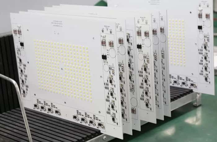
Inspection Methods at Each Production Stage
- Solder Paste Inspection (SPI) — Before placement — Measures paste volume, area and thickness to prevent insufficient or excessive solder, a common cause of LED failures
- Visual Inspection — After placement — Trained operators check for missing components, solder bridges, misaligned LEDs and contamination
- AOI (Automated Optical Inspection) — After soldering — High-resolution cameras capture the board from multiple angles; software detects solder quality issues, placement errors and polarity reversals
- X-Ray Inspection — After soldering — Reveals internal solder connections hidden under BGA packages or LEDs with underside terminations; essential for high-density designs
- Flying Probe / ICT — Before functional test — Electrical testing verifies continuity, shorts and open circuits on the assembled board
- Functional Testing — Final stage — The assembled LED board is powered on and tested for actual light output, current draw and color consistency
Quality Standards We Follow
IPC-A-610
Acceptability of electronic assemblies — defines criteria for solder joint quality, component placement accuracy and board cleanliness
IPC J-STD-001
Soldering requirements for electronic assemblies — specifies materials, methods and verification criteria for reliable solder connections
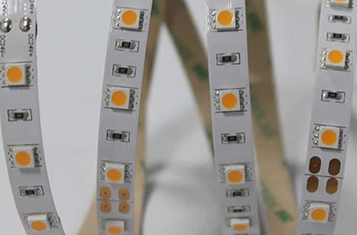
Key Takeaway: Manufacturers following IPC standards produce LED PCB assemblies with predictable reliability and consistent performance. Always confirm that your assembly partner follows IPC-A-610 and J-STD-001 before placing an order.
LED PCB Assembly FAQ
Why is aluminum the most common substrate for LED PCB assembly?
Aluminum offers excellent thermal conductivity (1.0–2.2 W/mK) at a reasonable cost, allowing it to dissipate heat from high-power LEDs without external heat sinks. It is rigid, durable and widely available, making it the best balance of performance and price for most LED lighting applications.
What SMD LED package sizes are commonly used in LED PCB assembly?
Common SMD LED packages include 2835, 3528, 5050, 5730 and 3030. The numbers refer to the LED dimensions in millimeters (e.g. 5050 = 5.0mm × 5.0mm). Larger packages generally handle higher power and produce more lumens. 5050 LEDs are popular for RGB color lighting, while 2835 and 5730 are common for high-efficiency white LED strips.
How does thermal management work in LED PCB assembly?
Thermal management transfers heat from LED junctions through the substrate into the surrounding environment. In aluminum LED PCBs, a thermally conductive dielectric layer moves heat from the copper circuit layer to the aluminum base, which acts as a heat spreader. This prevents heat buildup that would otherwise cause lumen depreciation, color shift and premature LED failure.
What inspection methods are used for LED PCB assembly?
LED PCB assembly typically uses visual inspection, AOI (Automated Optical Inspection), X-ray inspection for hidden solder joints, solder paste inspection (SPI) before placement, flying probe or ICT for electrical continuity testing, and functional testing to verify light output and electrical performance. These methods are guided by IPC-A-610 and J-STD-001 quality standards.
Can LED PCB assemblies be produced in custom shapes and sizes?
Yes. LED PCBs can be fabricated in rectangular strips, circular boards, star shapes, hexagonal patterns and irregular outlines to fit specific lighting fixtures. The aluminum substrate can be routed or punched into custom geometries. Common applications include LED strips, downlight panels, automotive light rings and architectural lighting modules.
What is the typical lead time for LED PCB assembly?
LED PCB assembly lead time depends on substrate type, LED package complexity, order volume and whether components are in stock. For prototypes and small batches using standard aluminum substrates and common SMD LEDs, lead times typically range from 3–7 days. Turnkey projects that include component sourcing may take 1–2 weeks depending on part availability.