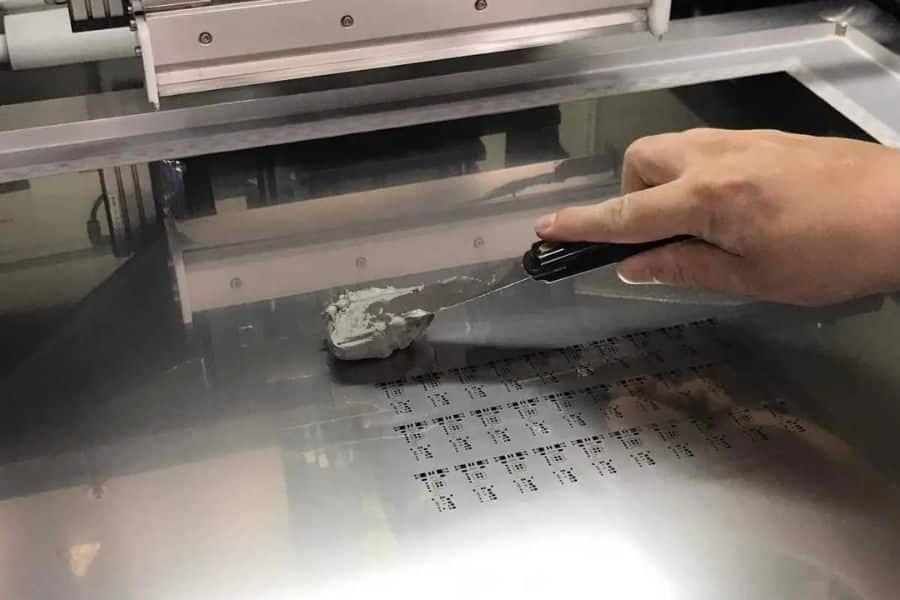
SMT Stencil Specifications & Capabilities
Compare six types of SMT stencils — prototype, framed, frameless, electroformed, nano-coated, and step stencils. PCBELEC fabricates laser-cut and electroformed stencils with ±0.007–0.008mm tolerance; lead time varies by stencil type (1–2 days for laser-cut, 5–7 days for electroformed, 3–5 days for step stencils).
SMT Stencil Specifications by PCBELEC
PCBELEC manufactures six categories of SMT stencils — prototype (0.06–0.3mm), framed, frameless, electroformed (±0.008mm), nano-coated, and step stencils. Laser-cut stencils use 304 stainless steel with ±0.007mm aperture tolerance and overall sizes up to 736×736mm; electroformed stencils use nickel with ±0.008mm tolerance. Lead time varies by type (1–2 days for laser-cut, 5–7 days for electroformed, 3–5 days for step stencils).

Laser-Cut Precision (±0.007mm)
6 Stencil Types Available
Lead Time Varies by Stencil Type
Compare All Six Stencil Types at a Glance
Compare the six SMT stencil types PCBELEC manufactures — prototype, framed, frameless, electroformed, nano-coated, and step stencils — by material, thickness, minimum aperture, maximum size, tolerance, and lead time. Choose the option that matches your board size, finest pitch, and production volume, or contact our engineering team for a recommendation.
| Stencil Type | Material | Thickness (mm) | Min Aperture | Max Overall Size | Tolerance | Lead Time |
|---|---|---|---|---|---|---|
| Prototype | 304 SS | 0.06 – 0.30 | 0.10 mm | 736 × 736 mm | ±0.007 mm | 1–2 days |
| Framed | 304 SS | 0.10 – 0.30 | 0.15 mm | 736 × 736 mm | ±0.007 mm | 1–2 days |
| Frameless | 304 SS | 0.10 – 0.30 | 0.15 mm | 280 × 380 mm | ±0.007 mm | 1–2 days |
| Electroformed | Nickel | 9 grades 0.025–0.30 | 0.04 mm | 510 × 800 mm | ±0.008 mm | 5–7 days |
| Nano-Coated | 304 SS | 0.10 – 0.30 | 0.10 mm | 736 × 736 mm | ±0.007 mm | 1–2 days |
| Step Stencil | 304 SS | Step-up/down 0.05–0.20 | 0.10 mm | Custom | ±0.010 mm | 3–5 days |
Prototype SMT Stencil Spec
Prototype SMT stencils are PCBELEC’s fastest-turnaround option for quick-turn and NPI builds. Laser-cut from 304 stainless steel, they support sheet thicknesses from 0.06 to 0.3 mm and apertures down to 0.10 mm with ±0.007 mm aperture tolerance. Standard lead time is 1–2 days.
| Parameter | Specification |
|---|---|
| Technology | Laser-Cut |
| Material | Stainless Steel |
| Sheet Thickness | 0.06 – 0.3mm |
| Min. Aperture | 0.10mm |
| Distance to Edge | 7mm |
| Overall Size | 736x736mm |
| Aperture Tolerance | ± 0.007mm |
| Lead Time | 1-2 days |
Framed SMT Stencil Spec
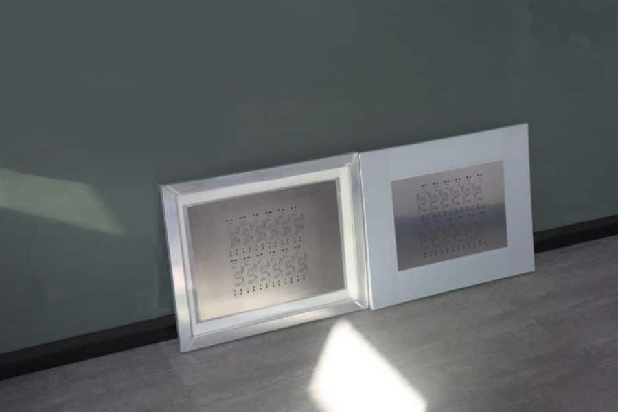
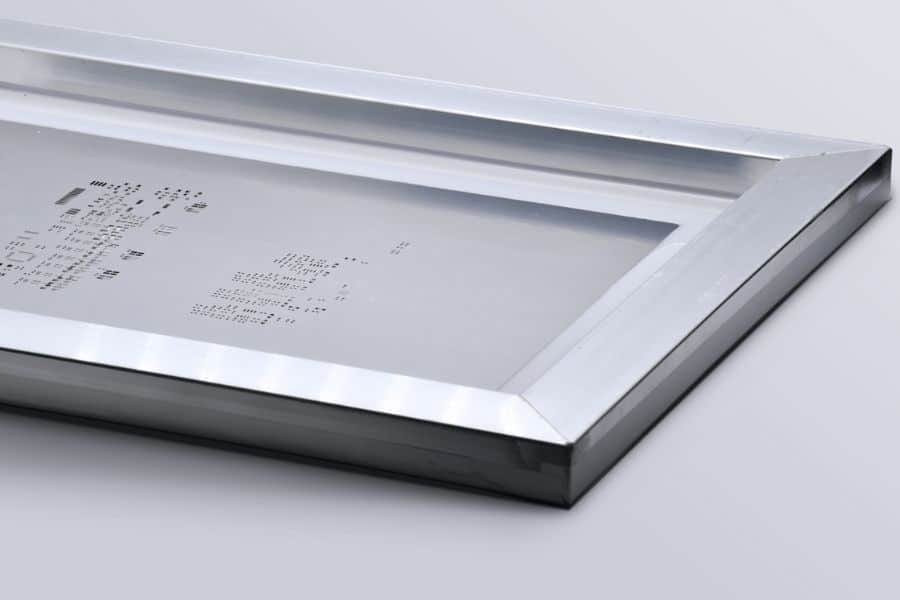
Framed SMT stencils are mounted on an aluminum frame for use with dedicated stencil printers on production lines. Laser-cut from 304 stainless steel, they support sheet thicknesses from 0.10 to 0.30 mm, apertures down to 0.15 mm, and overall stencil sizes up to 736 × 736 mm with ±0.007 mm aperture tolerance. Standard lead time is 1–2 days.
| Parameter | Specification |
|---|---|
| Technology | Laser-Cut |
| Material | Stainless Steel |
| Sheet Thickness | 0.10-0.30mm |
| Frame Material | Aluminum |
| Frame Size | 23″*23″, 23″*29″, 29.5″*29.5″ |
| Min. Aperture | 0.15mm |
| Distance to Edge | 10mm |
| Overall Size | 736x736mm |
| Aperture Tolerance | ± 0.007mm |
| Lead Time | 1-2 days |
Framed PCB Stencil Specifications
Framed SMT stencils are available in standard aluminum frame sizes from 7″ × 7″ up to 20″ × 20″ outer dimensions. The table below lists the outer frame size and the corresponding internal stencil area for each standard option, in both inches and millimeters. Match the frame size to your stencil printer’s holder; if you need a custom frame size, contact our engineering team.
| Frame Size (Outer) | Internal Size | ||
|---|---|---|---|
| Frame Size (Outer) | Internal Size | Frame Size (Outer) | Internal Size |
| 7″x 7″(178x178mm) | 6″x 6″(152x152mm) | 13.8″x 13.8″(350x350mm) | 11.8″x 11.8″(300x300mm) |
| 8″x 8″(203x203mm) | 7″x 7″(178x178mm) | 14.5″x 14.5″(370x370mm) | 12.6″x 12.6″(320x320mm) |
| 9″x 9″(228x228mm) | 8″x 8″(203x203mm) | 15″x 15″(380x380mm) | 13″x 13″(330x330mm) |
| 10″x 10″(254x254mm) | 9″x 9″(228x228mm) | 15.75″x 15.75″(400x400mm) | 13.8″x 13.8″(350x350mm) |
| 11″x 11″(280x280mm) | 10″x 10″(254x254mm) | 17.7″x 17.7″(450x450mm) | 15.7″x 15.7″(400x400mm) |
| 12″x 12″(304x304mm) | 11″x 11″(280x280mm) | 19″x 19″(480x480mm) | 17″x 17″(430x430mm) |
| 12.5″x 12.5″(320x320mm) | 11.5″x 11.5″(290x290mm) | 19.7″x 19.7″(500x500mm) | 17.7″x 17.7″(450x450mm) |
| 13″x 13″(330x330mm) | 12″x 12″(304x304mm) | 20″x 20″(510x510mm) | 18″x 18″(457x457mm) |
Framed PCB Stencil Frame Size Guide
Select a frame size that is compatible with your stencil printer or tensioning system. The table below shows standard outer aluminum frame dimensions and the corresponding usable stencil area. Please confirm your printer holder requirements before ordering; custom frame sizes may be reviewed on request.
| Frame Size (Outer) | Usable Stencil Area (Internal) | ||
|---|---|---|---|
| Inches | Millimeters | Inches | Millimeters |
| 7″ × 7″ | 178 × 178 mm | 4″ × 4″ | 102 × 102 mm |
| 10″ × 10″ | 254 × 254 mm | 7″ × 7″ | 178 × 178 mm |
| 12″ × 12″ | 305 × 305 mm | 9″ × 9″ | 229 × 229 mm |
| 15″ × 15″ | 381 × 381 mm | 12″ × 12″ | 305 × 305 mm |
| 16″ × 16″ | 406 × 406 mm | 13″ × 13″ | 330 × 330 mm |
| 18″ × 18″ | 457 × 457 mm | 15″ × 15″ | 381 × 381 mm |
| 20″ × 20″ | 510 × 510 mm | 17″ × 17″ | 432 × 432 mm |
| Custom | Custom | Based on drawing | Based on drawing |
Frameless SMT Stencil Spec
PCBELEC’s frameless SMT stencils are laser-cut from stainless steel, with stencil thicknesses from 0.06 to 0.3 mm, a minimum cut width of 0.05 mm, and a maximum size of 280 × 380 mm. Fiducial and panelized data are supported. Delivery is listed as 1–2 days.
| Parameter | Specification |
|---|---|
| Technology | 100% laser cut |
| Material Used | Stainless Steel |
| Stencil Thickness | 0.06 ~ 0.3 mm |
| Minimum Cut Width | 0.05 mm |
| Maximum Size | 280 X 380 mm |
| Allow for Fiducial Data | Yes |
| Allow for Panelized Data | Yes |
| Delivery | 1 ~2 Day |
Electroformed Stencil Spec
PCBELEC’s electroformed stencils are manufactured from nickel using an electroforming process. Available sheet thicknesses range from 0.025 to 0.30 mm, with a minimum aperture of 0.04 mm, an overall size of 510 × 800 mm, and an aperture tolerance of ±0.008 mm. Lead time is 5–7 days.
| Parameter | Specification |
|---|---|
| Technology | Electroforming |
| Material | Nickel |
| Sheet Thickness | 0.025, 0.04, 0.05, 0.06, 0.08, 0.10, 0.15, 0.20, 0.25, 0.30 mm |
| Min. Aperture | 0.04 mm |
| Overall Size | 510 × 800 mm |
| Aperture Tolerance | ±0.008 mm |
| Lead Time | 5–7 days |
Step Stencil Spec
PCBELEC’s step stencils combine laser cutting with etched steps in stainless steel for boards mixing fine-pitch components and large power pads. Base sheet thickness ranges from 0.10 to 0.30 mm, with an aperture tolerance of ±0.007 mm and a step tolerance of ±0.010 mm. Overall stencil size is 736 × 736 mm, and lead time is 3–5 days.
| Parameter | Specification |
|---|---|
| Technology | Laser-Cut + Etched Step |
| Material | Stainless Steel |
| Base Sheet Thickness | 0.10–0.30 mm |
| Step Depth | 0.02–0.08 mm per step (max ±0.15 mm) |
| Min. Aperture | 0.10 mm |
| Distance to Edge | 7 mm |
| Overall Size | 736 × 736 mm |
| Aperture Tolerance | ±0.007 mm |
| Step Tolerance | ±0.010 mm |
| Lead Time | 3–5 days |
| Best For | Boards mixing fine-pitch & large power pads |
Nano-Coating Stencil Spec
PCBELEC’s nano-coated stencils use stainless steel with a 1.5 μm nano coating. Specifications include a stencil life of more than 100,000 prints and various aperture positions, with LED backlighting listed as an application. Lead time is 1–2 days.
| Parameter | Specification |
|---|---|
| Technology | Nano Coating |
| Material | Stainless Steel with Nano Coating |
| Coat Thickness | 1.5 μm |
| Stencil Life | > 100,000 prints |
| Aperture Position | Various Aperture Positions Available |
| Application | LED backlighting |
| Aperture | 1,000,000 |
| Lead Time | 1–2 days |


Free DFM Review
ISO 9001 & IATF 16949
24h Global Shipping
±0.007mm Tolerance
Need SMT Assembly Service Too?
Once your stencil is ready, get your boards assembled at pcbjhy.com. Free DFM, one-on-one engineering support, BGA/QFP fine-pitch capability.
SMT Stencil Design & Ordering Notes
To help us manufacture your SMT stencil accurately and quote it without delay, please provide the required production files and order details. The notes below apply to standard laser-cut stencils and identify the additional information needed for framed, frameless, electroformed, nano-coated, or step stencil requests.
Required Production Files
- Provide the solder-paste Gerber layer for the required PCB side: top, bottom, or both.
- Include the board outline, panel outline, fiducial marks, and tooling features when applicable.
- Clearly identify the required stencil side when files are supplied for both PCB sides.
- Submit production-ready Gerber or ODB++ data; PDF drawings may be included as reference files.
Aperture & Thickness Requirements
- State the required stencil thickness, or request a recommendation based on the finest pitch, pad geometry, and component mix.
- Identify any required aperture reductions, home-plate designs, window-pane patterns, or other aperture modifications.
- Highlight the smallest apertures and critical packages, such as fine-pitch QFN, BGA, micro-BGA, or 01005 components, when applicable.
- Request an engineering review before production when aperture design or solder-paste release is critical.
Stencil Type-Specific Details
- Framed: Confirm the printer-compatible frame size and required usable stencil area.
- Frameless: Provide tension-frame or printer-holder requirements, including the compatible foil size.
- Electroformed: Identify critical fine-pitch, micro-aperture, or paste-release requirements for engineering review.
- Nano-coated: Identify the intended application and any durability or paste-release requirements.
- Step stencil: Provide a step map or mechanical drawing showing each step area, base thickness, final thickness, and required step depth.
Quotation & Delivery Details
- Provide the required quantity, destination country or region, and requested delivery date.
- State whether the stencil is intended for prototype, NPI, or production use.
- Include any packaging, shipping-account, or labeling requirements with your quote request.
- Final manufacturability, lead time, and delivery arrangements are confirmed after review of the complete order information.
Frequently Asked Questions About SMT Stencil Capabilities
PCBELEC laser-cut stencils achieve ±0.007mm (7 µm) aperture tolerance using 0.0007" laser spots on type 304 stainless steel. This supports fine-pitch QFP down to 0.4 mm pitch and 0201 passive components with consistent solder paste release.
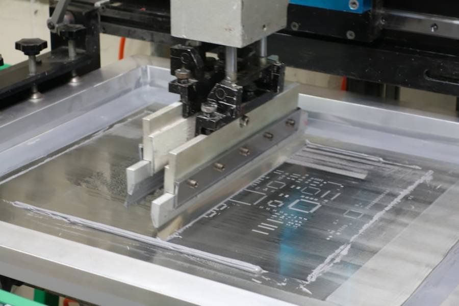
We produce laser-cut stencils with maximum overall dimensions of 736 × 736 mm. Framed stencils match standard DEK, MPM, and Yamaha printer profiles (see Table 3 for the 17-frame reference). Frameless sheets up to 280 × 380 mm support manual printing.
Laser-cut stencils use a 304 stainless steel sheet with a focused laser beam — faster, lower cost, suited to most SMT applications. Electroformed stencils are nickel-based, support finer apertures (down to 0.04 mm), better wall smoothness (±0.008 mm), and are required for 0201, uBGA, and flip-chip.
Prototype and frameless stencils are available in 0.06, 0.08, 0.10, 0.12, 0.15, 0.20, 0.25, and 0.30 mm thicknesses. Match the thickness to your smallest component pitch — 0.10–0.12 mm for 0.5 mm QFP/BGA, 0.08 mm for 0201/01005. Step-up/down regions can combine thicknesses on one stencil.
Prototype and frameless laser-cut stencils ship within 24 hours; framed stencils ship within 1–2 business days. Electroformed stencils require 5–7 business days due to the plating process. Bulk orders may extend to 3–5 business days; contact our team for an exact timeline.
Nano-coating applies a 1.5 µm anti-adhesion layer to aperture walls, increasing print life beyond 100,000 prints — recommended for high-density boards with 01005, 0201, BGA, and uBGA components. The coating prevents solder paste sticking and reduces cleaning cycles on fine-pitch assemblies.