Through-Hole PCB Assembly Services
Dependable through-hole PCB assembly for prototypes, small batches, and production runs — with mixed SMT + THT capability, wave soldering, selective soldering, and skilled hand soldering for high‑reliability electronic products.
- Pure through-hole and mixed SMT + through-hole PCB assembly on a single board.
- Wave soldering, selective soldering, and manual hand soldering for complex THT components.
- Ideal for connectors, transformers, power components, and vibration‑prone applications.
- From engineering prototypes to repeat production with controlled, inspection‑driven processes.
Why Choose JHYPCB
Why JHYPCB Is a Reliable Partner for Through-Hole PCB Assembly
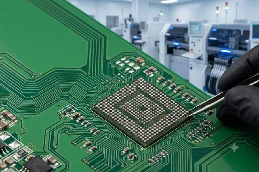
Through-hole assembly is often used in applications where mechanical strength, power handling, and long-term reliability matter most. JHYPCB supports these projects with practical THT process experience, flexible production options, and quality-focused assembly control from prototype builds to repeat production.
Built for High-Reliability Assemblies
Through-hole components are widely used in boards that must withstand vibration, mechanical stress, heat, or higher current loads. We support these requirements with process selection and assembly control suited to reliability-critical electronic products.
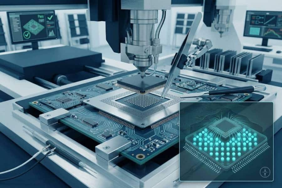
Wave, Selective, and Hand Soldering Support
Different through-hole boards require different soldering methods. JHYPCB supports wave soldering, selective soldering, and manual hand soldering to match component layout, board complexity, and production needs.
Prototype to Production Flexibility
We support through-hole PCB assembly for engineering prototypes, pilot runs, low-volume orders, and ongoing production. This helps customers move from validation to repeat manufacturing with a more consistent supply path.
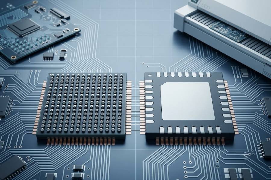
Mixed SMT + Through-Hole Capability
Many modern boards combine SMT and through-hole components on the same PCB. JHYPCB supports mixed-technology assembly so customers can work with one manufacturing partner for both compact layouts and mechanically demanding components.
Through-Hole PCB Assembly Capabilities
From manual insertion and hand soldering to wave soldering, selective soldering, and mixed-technology assembly, JHYPCB supports through-hole PCB assembly across prototype builds, low-volume production, and repeat manufacturing. Our capabilities are designed for boards that require stronger mechanical retention, higher power handling, or dependable performance in demanding environments.
Assembly Types
Pure through-hole PCB assembly, mixed SMT + THT assembly, and project-based builds for prototypes, pilot runs, and ongoing production.
Component Handling
Support for axial, radial, connectors, transformers, relays, pin headers, power components, and other leaded parts used in reliability-focused electronic assemblies.
Soldering Processes
Manual hand soldering, wave soldering, and selective soldering selected according to board layout, production scale, and solder joint requirements.
Production Volume
Engineering prototypes, low-volume assembly, pilot production, and repeat manufacturing with process consistency from build to build.
Mixed-Technology Support
Combined SMT and through-hole PCB assembly for boards that require compact layouts together with mechanically robust or high-power through-hole components.
Quality Control
Inspection-focused assembly workflows with attention to solder joint quality, component placement, workmanship consistency, and customer-specific build requirements.
Compliance Options
RoHS-compliant assembly options and process flexibility for different material, soldering, and application requirements.
Value-Added Services
Capability extension can include testing support, conformal coating, programming, labeling, and other assembly-related requirements depending on project needs.
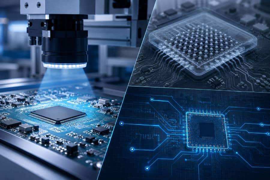
Mixed SMT + Through-Hole PCB Assembly
Many electronic products require both SMT and through-hole components on the same board. JHYPCB supports mixed-technology PCB assembly to help customers combine compact circuit layouts with stronger mechanical retention, broader component selection, and process flexibility for more demanding applications.
One Board, Multiple Process Needs
Mixed assembly is ideal when a PCB includes dense SMT devices together with connectors, transformers, relays, pin headers, or other through-hole parts that require stronger solder joints and mechanical support.
Better Design Flexibility
By combining SMT and THT on the same board, customers can support compact layouts without giving up the durability and application fit of leaded components where they are still needed.
More Suitable for Demanding Applications
Mixed-technology PCB assembly is often used in products where electrical density, mechanical reliability, and broader component compatibility all matter in the same design.
Typical Process Flow
- SMT placement and reflow soldering for surface-mount components
- Through-hole insertion for leaded components
- Wave soldering, selective soldering, or hand soldering based on layout needs
- Inspection and final build verification before shipment
Why It Matters
- Supports compact board design and higher functional density
- Improves mechanical robustness for connectors and larger components
- Expands component options across one PCB design
- Helps balance manufacturability, reliability, and application requirements
Typical Applications for Through-Hole PCB Assembly
Through-hole PCB assembly remains a practical choice for products that must deliver stronger mechanical stability, higher power handling, and dependable long-term performance. It is widely used in industrial, automotive, power, communications, medical, and other reliability-focused electronic applications.
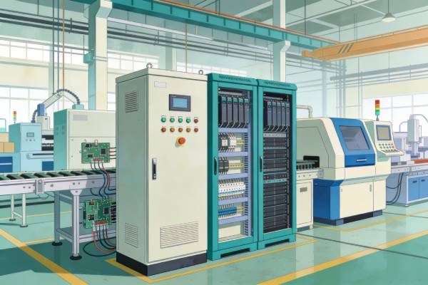
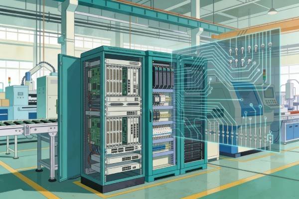
Industrial Control Systems
Used in PLCs, control modules, factory automation equipment, and rugged electronic systems where vibration resistance, long service life, and stable field performance are important.
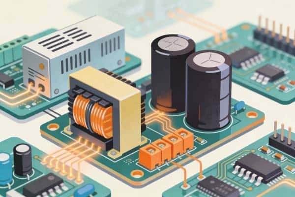
Power Supply & Power Electronics
Suitable for boards with transformers, large capacitors, terminal blocks, relays, and other components that require stronger mounting, higher current handling, or better thermal endurance.
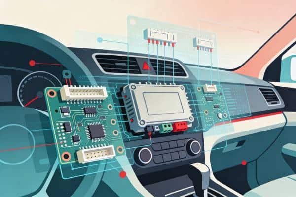
Automotive Electronics
Common in automotive control units, lighting systems, power distribution modules, and other electronics exposed to vibration, temperature change, and demanding operating conditions.
Communications Equipment
Applied in networking, telecom, and signal-related products that rely on robust connectors, dependable solder joints, and reliable operation over extended service cycles.
Medical & Reliability-Critical Devices
Used in equipment where assembly quality, component stability, and dependable electrical performance are essential to overall product reliability and maintenance confidence.
Aerospace, Defense & Harsh Environments
Appropriate for systems that must tolerate mechanical shock, continuous vibration, or harsh environmental stress where strong through-hole connections offer added design security.
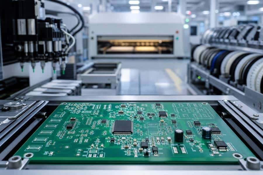
Assembly Workflow
Through-Hole PCB Assembly Process
A clear and controlled assembly workflow helps reduce build errors, improve solder joint consistency, and support smoother delivery from prototype validation to repeat production. At JHYPCB, through-hole PCB assembly follows a structured process that can be adjusted according to board design, component mix, soldering requirements, and production volume.
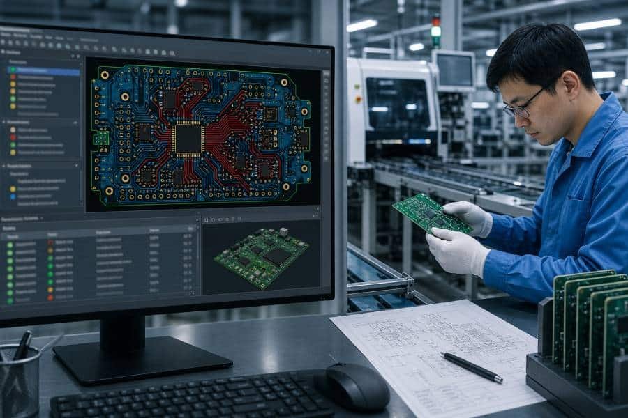
DFM and Document Review
We begin by reviewing Gerber files, BOM data, assembly drawings, and project requirements to confirm manufacturability, component suitability, and the most appropriate assembly path for the board.
Component Preparation and Material Control
Components are sourced or prepared according to the approved BOM, then checked for quantity, specification, and incoming quality before assembly begins.
Component Insertion
Through-hole components are inserted into the PCB in the required positions, either manually or through controlled assembly methods, with attention to orientation, lead fit, and placement accuracy.
Soldering Process Selection
Depending on board layout and production needs, soldering may be completed by wave soldering, selective soldering, or skilled hand soldering, especially for mixed-technology boards or assemblies with tighter spacing.
Inspection and Quality Verification
After soldering, each assembly is checked for solder joint quality, component placement, workmanship consistency, and customer-specific build requirements. Additional inspection or testing can be arranged depending on the project.
Final Assembly Completion and Shipment
Once the boards pass the required checks, they move to final handling, packaging, and shipment, supporting a smoother transition from prototype approval to low-volume or repeat production delivery.
Quality Control & Inspection for Through-Hole PCB Assembly
Reliable through-hole PCB assembly depends not only on the soldering method, but also on disciplined inspection and process control throughout the build. JHYPCB applies quality-focused checks from incoming materials to final verification to help improve solder joint consistency, assembly workmanship, and overall product reliability.
Incoming Material Check
BOM-related components and bare PCBs are checked before assembly to confirm quantity, part consistency, visible condition, and readiness for production.
Process Control During Assembly
Assembly steps are monitored to reduce handling errors and maintain stable workmanship during insertion, soldering, and mixed-technology operations.
Solder Joint Inspection
Through-hole solder joints are reviewed for wetting quality, solder coverage, bridging, excess solder, insufficient fill, and other visible defects that may affect long-term reliability.
Visual Inspection and Workmanship Review
Component orientation, lead trim condition, placement consistency, and overall assembly workmanship are checked to help ensure each board matches the approved build intent.
Additional Inspection or Testing
Depending on project requirements, additional inspection methods or electrical verification steps can be arranged to strengthen quality assurance before delivery.
Final Verification Before Shipment
Completed assemblies go through final review before packing and shipment to help reduce avoidable defects and improve delivery consistency.
What We Need to Start Your Through-Hole PCB Assembly Project
Submitting a complete and organized data package helps speed up quotation, reduce engineering questions, and improve build accuracy from the start. For through-hole PCB assembly, clear file preparation is especially important when the project includes leaded components, mixed-technology assembly, polarity-sensitive parts, or special soldering instructions.
Gerber Files
Please provide complete Gerber data for the PCB, including all required manufacturing layers and the latest confirmed revision.
Bill of Materials (BOM)
The BOM should list part numbers, quantities, reference designators, and key component details needed for sourcing, verification, and assembly planning.
Assembly Drawing
Assembly drawings help clarify component orientation, polarity marks, reference locations, and special build notes that may not be obvious from the PCB files alone.
Drill Files
For through-hole projects, drill information is important for confirming hole positions, diameters, and other hole-related requirements tied to component insertion.
Pick-and-Place / Centroid File (If Applicable)
If the project includes SMT or mixed-technology assembly, placement data helps support programming and coordinate-based assembly preparation.
Special Instructions or Test Requirements
Please include any customer-specific assembly notes, approved alternatives, labeling requests, functional test requirements, or special process instructions relevant to the project.
Ready to send your files? Contact our assembly team for a quote.
Through-Hole PCB Assembly FAQ
Below are some common questions customers ask when evaluating through-hole PCB assembly services, from process selection and mixed-technology support to file preparation, lead time, and quotation requirements.
Through-hole PCB assembly is often a better choice when the product requires stronger mechanical attachment, better support for larger or heavier components, or higher durability in demanding environments. It is commonly used for connectors, transformers, relays, terminal blocks, and other parts that benefit from reinforced board mounting.
Yes. Many electronic products use both SMT and through-hole components on the same PCB, and mixed-technology assembly is a common requirement for practical manufacturing. Depending on the board structure and component distribution, the assembly process may combine SMT placement, through-hole insertion, and wave soldering, selective soldering, or hand soldering as needed.
A quotation or production review usually requires Gerber files, a BOM, and assembly drawings at minimum. For projects that include SMT or mixed assembly, pick-and-place data, drill information, testing requirements, and any special assembly notes can also help improve quotation accuracy and production readiness.
Yes. Through-hole PCB assembly is often used for prototypes, pilot builds, and low-volume production, especially when products involve larger leaded components or require more manual process control. This makes it suitable for engineering validation, early production runs, and specialized industrial applications.
Lead time usually depends on file completeness, PCB fabrication status, component sourcing, assembly complexity, and inspection requirements. Compared with highly automated SMT-only projects, through-hole assembly may take longer in some cases because insertion and soldering can involve more manual work or selective processing steps.
Yes, component sourcing can be supported as part of the PCB assembly process when BOM information is provided clearly. Accurate part numbers, approved alternatives, and complete specifications help reduce sourcing delays and improve overall quotation and delivery efficiency.
In many cases, through-hole assembly can involve higher labor cost than SMT because it may require manual insertion, hand soldering, or slower selective soldering steps. Actual cost depends on board complexity, component mix, quantity, and whether the project is prototype, low-volume, or repeat production.
Through-hole solder joint quality is typically supported through material checks, process control, soldering method selection, and post-assembly inspection. Key quality concerns usually include proper wetting, sufficient fill, reduced bridging risk, correct component orientation, and acceptable overall workmanship according to project requirements.
Ready to Start Your
Through-Hole PCB Assembly Project?
Whether you need prototype through-hole PCB assembly, mixed SMT + THT support, or repeat production for reliability-focused products, JHYPCB is ready to review your project requirements and provide a practical quotation path.
Please send your Gerber files, BOM, assembly drawings, and any special requirements so our team can evaluate your project more efficiently and respond with a suitable assembly solution.